The 08M2 chip from the PICAXE range of microprocessors is a good place to start teaching yourself about programming a wide range of operations. It is similar to the chip used by Action Electronics for all their products.
PICAXE Tutorial
1. Power source
2. PC download jack
3. Leg and Pin numbering
4. My 1st ‘Hallo’ computer code
5. Output by LED
a) Sourcing Current
b) Sinking Current
c) Source and Sinking Current
6. Input by mechanical switch
7. Input by variable resistor
8. Input by heat and light sensors
9. Other inputs
10. Switch pulse counter
11. Play, Sound, Tune
12. Flashing light using PULSOUT
13. Use of R/C Transmitter/Receiver as source of input.
a) Ch5 Fixed input switch O/I.
b) Ch3 Variable inputs(throttle)
c) Ch3 Increasing frequency to improve accuracy.
d) Ch3 Joystick central position.
e) Ch4 Motor controller H Bridge.
f) Ch4 Motor control.
g) Ch4 Three position motor control.
14. Throttle Ch3 controlling motor speed in one direction.
a) Ch3 Linear speed increase off – max forwards.
b) Ch3 Linear speed decrease max reverse – off.
15. Ch4 controlling motors
a) Ch4 Linear forwards Central off [half codes].
b) Ch4 Linear reverse Central off [half code].
c) Ch4 Linear speed. Max reverse – off – max forwards.
d) Ch4 Non linear speed increase 0ff - max forwards [half code]
e) Ch4 Non linear speed. Max reverse – off – max forwards.
16 Servopos Joystick output to Servo
a) Output to Picaxe
b) Joystick and Variable Resistors control circuit
c) 14m2 Motor contro; PCB
d) Receiver controlling motor
17 Photo interrupter
18 Slotted disc turn counter. TBA
19 Variable resistor feedback loop. TBA
20 Metronome for Tai Chi
Information Sources
Picaxe Microcontroller Projects by Ron Hackett
Picaxe Manuals 1, 2 & 3 from www.picaxe.co.uk
Picaxe Forum
1. Power source
The PICAXE microprocessors has a maximum voltage of 5.5v. My choice was for 3 x AA alkaline batteries giving 4.5v housed in a switched box.
Manual 1 pg 25.

2. PC download jack
Axe 027 USB cable is used to connect the PC to the processor, a special USB plug and a 3.5mm mini plug. A 3.5mm stereo jack socket was fitted to a 4 x 12 hole stripboard. The 5 holes have to be drilled out 1.6mm. The longer legs of the Header Block have to be inserted through the stripboard.
Hackett pg 11, Manual 1 pg 27

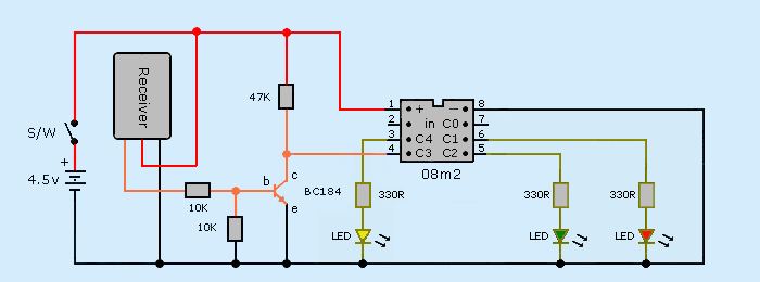
3. Leg and Pin Numbering

M2 parts pin notation see Manual 1 page 10/11
The left Chip shows the Leg numbers 1 — 8 and right Chip shows the Pin numbers C.0 to C.4. Just to confuse you they are in the reverse order.
The 08M2 chip has two dedicated pins for power supply +ve 1, -ve 8 (common ground) and two for programming pins 2 and 7. The five legs 3 to 7 (C.4 to C.0) are used for Inputs and Outputs. Pin 7 (C.0) has a combined use but not simultaneously.
It is good practice when learning to make a ”Comment“ on the line of code to the leg number used.
high C.2 ;leg 5
Manual 1 pg 27/71, Manual 2 pg 27
4. My first "Hallo" computer code
Main:
high C.2 ; i/o pin 2 = physical ic pin 6
pause 750
low C.2
pause 1500
goto main
Main: Label or Address of a specific piece of computer coding. Can be reused.
: Colon used to show end of a line of code. Used to combine lines of short code onto one line.
high C.2 Makes pin 2 an Output and high. Can source or sink an external circuit.
low C.2 Makes pin 2 an Output and low. Can source or sink an external circuit.
pause Pauses the program for a specified time. 1000=1sec
goto Permanent jump to a specified address/label. Loop back to start.
High is a voltage above 80% of power supply. Low is 20% below.
5. Output by LED's
The two fundamentals of LED’s are they only work in one direction and their voltage is restricted.
The symbol looks like an arrow with a bar at the pointed end. The arrow shows the direction the current must flow through the LED.
If you look at an LED one wire is longer than the other. The long one goes to the +ve supply. If the wires have been cut, you will see a flat on the flange next to the -ve terminal.
To remember which is positive PLANS = Positive is Long And Negative is Short. This is used to get the symbol for a battery the corrrect way round.
The bar is used to indicate the band on normal diodes.
It is normal practice to add a resistor in series to the LED to restrict the voltage across the LED. Search their specification and look for their Forward Typical Voltage. 2v is a good guide.
Typical LED spec is 10mA at 2v. With a 4.5v supply, the voltage across the ballast resistor is 2.5v. Resistor value = 2.5 / 0.01 = 250R. Using 330R, the voltage across the LED = 4.5 - 330 x 0.01 = 1.2v
The data transfer jack socket circuit uses leg 2 for data in and leg 7 (C.0) for data out.
The 22K resistor drops the current into the Chip. The 10K grounds the data signal when it goes low otherwise the chip will not work correctly.
Grounding make the terminal’s voltage near to the power supply negative.
Manual 1 pg 43/72.
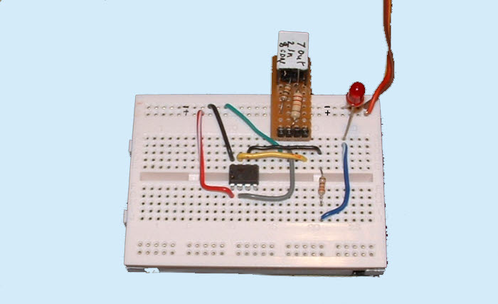
a. Sourcing Current
A LED is added as the output to pin 6 (C.1). A 330R resistor is added to give 2v across the LED.
The current comes from leg 6 (C.1) through the resistor and LED to −ve ground. The LED is ”Sourcing“ the current from the Chip. Current passes through the LED in the direction of the arrow (triangle point).
Main: ; title/label of the block of code
high C.1 ; output C.1 (leg 6) goes high and LED On. C.1 = 1
pause 750 ; pauses 750ms
low C.1 ; output C.1 goes low and LED Off. C.1 =0
pause 1500 ; pauses 1.5s
goto main ; loops back to beginning and repaets code until stopped
Notes
Main: Label or Address of a specific piece of computer coding. Must end in :
high C.1 Makes C.1 an Output and high. Can source or sink an external circuit.
low C.1 Makes C.1 an Output and low. Can source or sink an external circuit.
pause Pauses the program for a specified time. 1000 = 1sec
goto Permanent jump to a specified address/label. Loop back to start.
High is a voltage above 80% (3.6v) of power supply. Low is below 20% (0.9v).
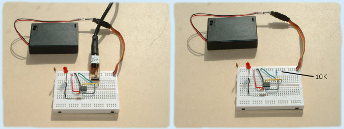
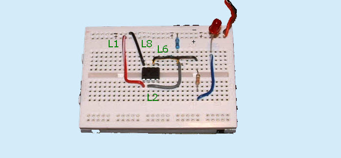
b. Sinking Current
In the circuit below the LED +ve is connected to the +ve rail and −ve to the Chip through the resistor. When Picaxe commands Output C.1 (leg 6) to go “Low” C.1 = 0 so the pin is as 0 volts ie. -ve
The LED will turn on as it is getting its current from +ve rail and its ground (negative) from the Chip. The LED is “Sinking” its current from the Chip.
If you remove the data input jack socket you must add a 10K resistor from pin 2 to ground shown below. Small blue resistor top centre. Manual 1 pg 29.
c. Sourcing and Sinking Current
With both LEDs connected to output pin 1 with the +ve of one and the −ve of the other, it is possible to turn one Off and the other On from the same output pin.
This shows that a negative source for components does not have to come from the Battery’s negative.
6. Input by mechanical switch
Electrical switches have mechanical contacts that do not close immediately but bounce before they completely close. This will send a string of on/off signals to the Chip which will cause errors. To solve this we add a piece of code to delay the output working until a steady On input (high) is achieved.
A 10K resistor is added to leg 2 to keep the Input Low when the switch is open
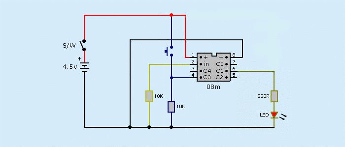
Switch is inputting a digital On/Off signal into Input C.3 (Leg 4) to control a LED through Output C.1 (leg 6)
To remove the switch bounce we are going to delay the input signal on C.3 by a few milliseconds before making the Output C.1 go high turning on the LED.
You could simply add pause, a time delay.
This piece of code introduces the if ... then conditional. If A = B then do C otherwise do D.
It also introduces “Variables”. This is a container used to store numbers between 0 and 255 (no negatives or fractions). Named b0, b1.
Will ‘overflow’ without warning if you exceed the 0 or 255 boundary values (e.g. 254 + 3 = 1) Manual 1 pg 52
The first thing we need to do at the start of a programme is to list any variables we are going to use in our code and give them a value. This code is only used once.
This is called Initialising and given the title init:
In this code we are using variable b0 to count the number of times a piece of code loops through itself before being switched to something else. This timing loop is in a sub-programme titled add
init:
let b0 = 0 ; initialise variable b0 giving it zero value
main:
if C.3 = 1 then add ; if no current, C.3 = 0 (off) so Output C.1 is low = Off
if C.3 = 0 then low 1 ; if current, C.3 = 1 (on) then goto sub-programme add
endif ; endif must be added to close the if statements
goto main ; if C.3 = 0 loop back to main
add: ; when C.3 = 1 (goes high) the following code is used
pause 100 ; delay of 100ms
let b0 = b0 + 1 ; add 1 to variable b0, b0 now = 1
if b0 < 5 then main ; if b0 less than 5 goto main else goto next line
high C.1 ; output C.1 (leg 6) goes high, LED On
goto main ; go back to main
Notes
Comments
Explanations of programme code for future reference. Started with ; or ' ignored by computer.
White spaces
Used for clarity only one is recognised by the computer. Manual 1 pg 74
if ... then
Used to find the state High/Low of an input and then do some operation. if pin4 = 1 then .. Similar to Yes/No decisions in flowcharts

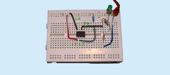
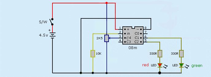
7. Input by variable resistor
Variable Resistors supply a varying analog voltage to the Chip which is converted into a digital value stored in a variable.
Readadc (adc means analog to digital converter). Read analogue voltage on Pin 3 and convert into a digital value stored in Variable b1.
Only use readadc pins 1, 2 & 4. Max impedance is 20K.
init:
b1 = 0
main:
readadc C.4, b1 ;reads analog value on C.4 into variable b1
if b1<75 then light1 ;if b1 is less than 75 then goto sub-programme light1
if b1<175 then light2 ;if b1 is less than 175 then goto sub-programme light2
goto light3 ;if b1 is greater than 175 then goto sub-programme light3
light1:
high C.1 ;C.1 goes high. LED Green On
low C.2 ;C. 2 goes low. LED Red Off
goto main ;loop back to main
light2:
low C.1 ;C. 1 goes low. LED Green Off
high C.2 ;C.2 goes high. LED Red On
goto main ;loop
light3:
high C.1 ;C.1 goes high. LED Green On
high C.2 ;C.2 goes high. LED Red On
goto main ;loop
At change points 75 & 175, VR values measured/calculated = 820R/730R & 1760R/1700R
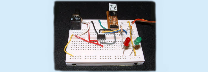
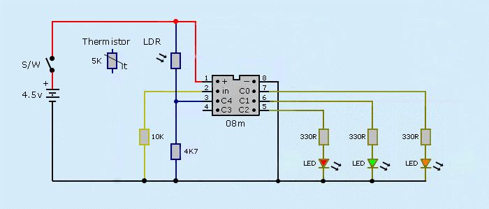
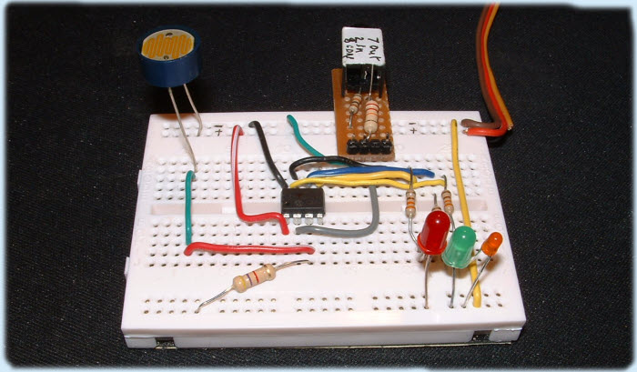
8. Input by Heat and Light Sensors
Any Sensor that changes its resistance depending on its environment works in the same way as a Variable Resistor. The 4K7 resistor is added to form a Potential Divider
init:
b1 = 0
main:
readadc C.4, b1 ; read value on C.4 into variable b1
if b1<100 then light1 ; if b1 is less than 100 then goto light1
if b1>101 and b1<200 then light2 ; if b1 is more than 101 and less than 200 then goto light2
goto light3 ; if b1 is greater than 200 then goto light3
light1:
high C.0 ; C.0 goes high. LED orange On
low C.1 ; C.1 goes low. LED green Off
low C.2 ; C.2 goes low. LED red Off
goto main ; loop
light2:
low C.0 ; C.0 goes low. LED orange Off
high C.1 ; C.1 goes high. LED green On
low C.2 ; C.2 goes low. LED red Off
goto main ; loop
light3:
low C.0 ; C.0 goes low. LED orange Off
low C.1 ; C.1 goes low. LED green Off
high C.2 ; C.2 goes high. LED red On
goto main ; loop
low 1 Adding ‘low’ code lines means only ‘high’ LED will light.
These sensors work by varying their resistance depending on temperature and light levels. Resistance falls as heat/light levels increase.
The sensors form the +ve side of a Potential Divider with a 4K7 resistor to ground (-ve). 4K7 was chosen as it matches the 5K Thermistor. The output is analogue not digital.
The programme code is similar to the “Variable Resistor” but the values between 0 - 255 will have to be found either by measuring resistance at the change over point or by trial and error.
One point of interest is how quickly these sensors respond to change. This can be found from “Rise and Fall” times if given.
Heat Sensor
5K NTC Disc Rapid 61-0410 £1.22
Light Sensor
NORPS12 LDR - Dark resistance 1M - @1ftc 5K4 min 12k6 max - Rapid 58-0132 £0.88p
LDR - r/fall 30ms - Rapid 58-0135 £0.72p (quicker r/fall time than above)
LDR details Manual 3 pg 29/30
Having made up these circuits I came across a Forum Post explaining how to calculate the fixed resistor’s value. 8K2 for light and 1K for heat. So the values I used in the code will have to be altered to suit the sensor’s specification.
Picaxe Forum Choosing resistor
Potential Divider
9. Other inputs
As I am interested in r/c marine applications, inputing using Infra red for remote control and distance sensing has been omitted. Many other types of sensors can be inputed using the previous methods.
10. Switch pulse counter
Code from Piers and others on Picaxe Forum
symbol bounce = b0 ; gives variable b0 the name bounce
symbol counter = b1 ; gives variable b1 the name counter
bounce = 0
counter = 0
bound:
if C.3 = 1 then add ; goto the switch bounce routine add
if C.3 = 0 then bound ; waits for input high
add:
pause 100
let bounce = bounce + 1
if bounce < 5 then bound
counting:
do
loop while C.3 = 1 ; Sit here while C.3 is high
inc counter ; increment by +1
if counter>5 then ; check for condition counter higher than 5
high C.1
endif
do
loop while C.3 = 0 ; Sit here while C.3 is low
goto counting ; loop back waiting for the next high/low
Symbol
Using variables such as b0 can become confusing in complex codes, you forget which one is which. Symbol is used to give a recognisable name to each variable ‘bounce’, ‘counter’. You could not use ‘count’ as this is a restricted word and would appear blue in the programme editor and through up an error message in the simulator.
Manual 2 page 232
bound
These two lines make the programme wait for input C.3 to go high
add
Switch contact bounce routine explained earlier in ‘2. Mecanical Switch’
Counting
do loop while C.3 = 1 makes the input wait in high state until it goes low. This could be up to 30min+.
When the input goes low the program goes to the next line.
inc counter This is short for counter = counter + 1 which increases the variable b1 (counter) by one each time it loops through.
if counter>5 then When the variable ‘counter’ reaches the value of 5 it exits out of the counting loop to the next line of code.
do loop while C.3 = 0 This line is to keep the output high even when the input goes low, keeping the output continually high.
11. Play, Sound, Tune
This is the basic circuit with pin 2 as the output. Either a Pizeo sounder from pin 2 to ground or a speaker with a 10µF polarised capacitor in series. A 33R resistor was put in series to reduce the current. The manual shows a 80w speaker but I tried the circuit with a 83R resistor but it reduced the sound.
There are three different Commands for making sounds, 4 pre-made tunes, simple sounds and musical tunes.
a. Play pre-made tunes
Picaxe has four tunes in its memory. See Man 2, pg 150.
Command - play 2, 1
2 — refers to output pin
1 — refers to embedded tunes 0 to 3. Only 1 works, Jingle Bells.
11b. Simple sounds
Note frequency and length can be changed to make “beep” sounds. See Man1, pg 76, man 2 pg 224, man 3 pg 11
Command - sound 2, (note, duration, note, duration, ...)
2 — refers to output pin
note - A variable or constant value of the Note's frequency
0 = silent, 1 — 127 ascending note, (128 — 255 give odd noises)
duration - Length of the Note 0 — 255 in 10ms steps
note and duration must be used in pairs
UP: ;Programme title. Notes increasing. Alternative to Main
for b0 = 10 to 120 step 4 ;FOR.. NEXT to loop from note 10 to 120 in steps of 4
sound 2, (b0,10) ;10 duration is used to go through programme quickly
if b0 = 100 then goto DOWN ;when b0 note is 100 goto DOWN programme.
next b0 ;if not, increases note value b0 by 4 each loop,
(Note- no endif)
DOWN: ;Sub-programme title. Notes decreasing.
pause 1500 ;pause for 1.5 sec, puts space between programmes
for b0 = 120 to 10 step -4 ;FOR.. NEXT to loop from note 120 to 10 in steps of -4
sound 2, (b0,10)
if b0 = 10 then goto CLIP ;when b0 note is 10 goto CLIP sub-programme.
next b0 ;if not, decreases note value b0 by 4 each loop,
pause 1500
(Note- no endif)
CLIP: ;Sub-programme
sound 2, (1,30,99,50,120,25,0,50,10,50,1,30,10,50,20,25,30,50)
pause 1500
goto UP ; loops back to UP, if left off the programme will stop
11c. Musical Tunes
Music can be created by writing your own directly, using the Tune Wizard or by importing pre-made tunes (mono Ringtones). See Man 2, pg 242-9, Man 3 pg 11.
Tunes are produced using standard musical scales in three octaves similar to a piano. Different tempos can be set for 1, 1/2, 1/4, 1/8.
Command — Tune 2, speed, (note, note, ...)
2 — refers to output pin
speed — variable or constant (1 — 15) creating the tune’s tempo.
note — In note $70, 7 refers to Octave (5 — 7). Last number/letter refers to the note (C, C#, D ...)
'LetItRain
tune 2, 6,($70,$7C,$7C,$7C,$73,$7C,$7C,$73)
Import Tunes
Tunes can be downloaded from PICAXE
Download ZIP file in new folder and unpack
a). For TV and Christmas Downloads as file.bas
1. Open PICAXE programme window. (no need to use Tune Wizard)
2. Select Open > Select your tune.bas> Open
3. Open in new window
4. Play = Simulate
5. Try altering speed. 1 is high
b).Mixed Tunes 1 — 3 Downloads as file.txt
1. Open PICAXE > New > Wizards > Ring Tones Tunes > Tune Wizard
2. File > Import Ringtone > select file.txt > open
3. Edit > Copy Basic
4. “Paste into main document” > Yes > Close Tune window
5. Play and change speed
c). Download free Abba SOS
1. Copy mono RTTTL Ringtone
2. Open PICAXE > New > Wizards > Ring Tones Tunes > Tune Wizard
3. Edit > Paste Ringtone
4. Edit > Copy Basic
5. Yes
6. Play
12. Flashing LED’s using PULSOUT
Using PULSOUT to control the length of LED pulse and delay.
Only one pulse will be obtained so a pause is added to create the delay before looping back to start again.
main;
pulsout C.1, 500 ; output on pin C.1 (leg 6), pulse 5ms
pause 200 ; pause 20ms
goto main ; loop back
pause — Man2 pg 145 — value in ms, 0 — 65535. eg 5000 = 5 sec
pulsout — Man 2 pg 206 — value in 10usec units, 0 — 65535. eg 150 = 1.5ms
Newbury Harbour Lighthouse. Oc (2) G 15s
Occulting twice, Green, every 15s. Sequence 7s on, 2s off, 4s on, 2s off
13. Use of R/C transmitter/receiver as a source of input
Sailservo has researched servos and receivers and found most information supplied to be suspect. To get an idea of real torque values divide manufacturer’s values by three or four. You should not use motors below about 50% speed drop so use this value when initially choosing your minimum duty cycle.
There is no such thing as a standard receiver output PWM pulse value. It differs between channels and even similar receivers
920us was the lowest found during tests and 2140us the highest.
1100 to 1900us is an approximate average with a range of 800us.
The joystick central position is not what you expect at 1500/1510us.
My Spektrum Dx/5e + orange receiver gave 1410 to 1430 depending on which side you moved from. That’s a 20us variation.
Set the trim buttons for each channel at their central position so you can make fine adjustments later.
When you are changing your code for different situations you may have to overlap the values to get correct working. In one instance, the motor suddenly went to max revs when it should have been off.
if w1 < 125 then = if w1 is less than 125
if w1 > 115 then = if w1 is more than 115
100us overlap
Altering frequency from 4 to 16MHz increases accuracy
if w1 < 561 then
if w1 > 559 then
Overlap is 560 +/- 1 = 10us
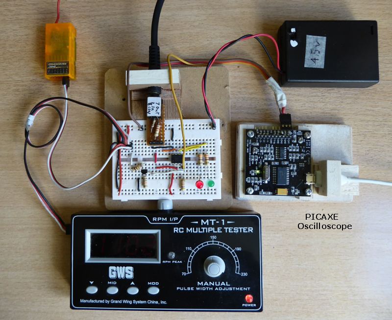
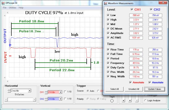
Buy the Picaxe oscilloscope (£12) to see what’s happening. Can also be used to check voltages in your circuit.
To find accurate values goto Utilities — Measurements — Waveform measurements.
If you change transmitter or receiver, you may have to alter your coding. Sailservo’s EPA End Point Adjuster could help if you don’t have a computer transmitter.
I’m afraid, it is all trail and error. The coding has been made to be easily adjustable.
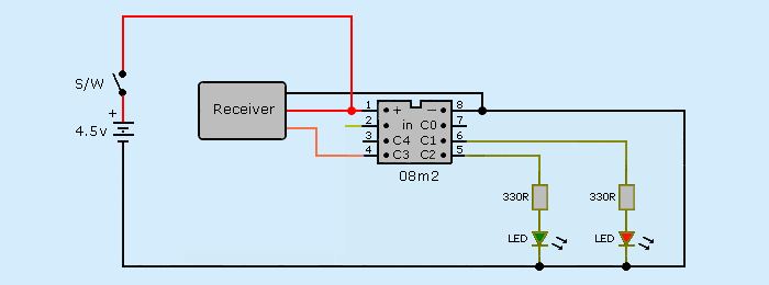
13a. Fixed inputs Ch5 switch
Simple circuit using the landing gear switch on the transmitter with the receiver outputing via Ch5. The pulse signal is feed into C.3 on leg 4. Two LED’s are feed from outputs C.1 & C.2.
Red led is on when switch @ 0 and green @ 1
Receiver power from Picaxe supply.
[CODE]
init:
w1 = 0
main:
pulsin C.3, 1, w1 'State 1 = low to high pulse starts timing
if w1 < 135 then redled 'if w1 is less than 135 then red LED
if w1 > 165 then greenled 'if w1 greater than 165 then green LED
redled:
low C.1 'leg 6 switch off green LED
high C.2 'leg 5 switch on red LED
goto main 'loop
greenled:
high C.1 'leg 6 switch on green LED
low C.2 'leg 5 switch off red LED
goto main 'loop
[/CODE]
Research carried out by SailServo has found that R/C receiver output pulses differ for all manufacturers, models and even channels.
Receiver output test. Checked with GWS MT1 Servo Tester.
Min/max range found was 920 to 2140us. (different receivers)
Max range 1149us.
Low values from 920 to 1320us.
High values from 1692 to 2140us.
Using 135 and 165 will cover all possible receivers as they are above and below all known values.
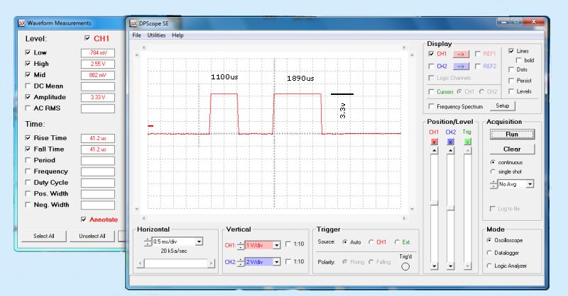
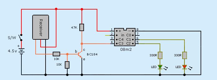
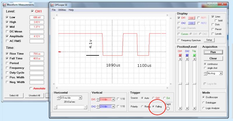
The pulse feed is directly from the receiver giving an amplitude of 3.3v. However, the positive pulse height is only 2.5v which is getting close to the minimum +2.0v for picaxe logic high. To avoid this problem a transistor is added between the receiver and picaxe. As the transistor reverses the polarity, the pulse is measured at the traing edge and the Pulsin state code has to be changed to a "0". Simlarly, change the button on the scope "Trigger - Polarity" to falling.
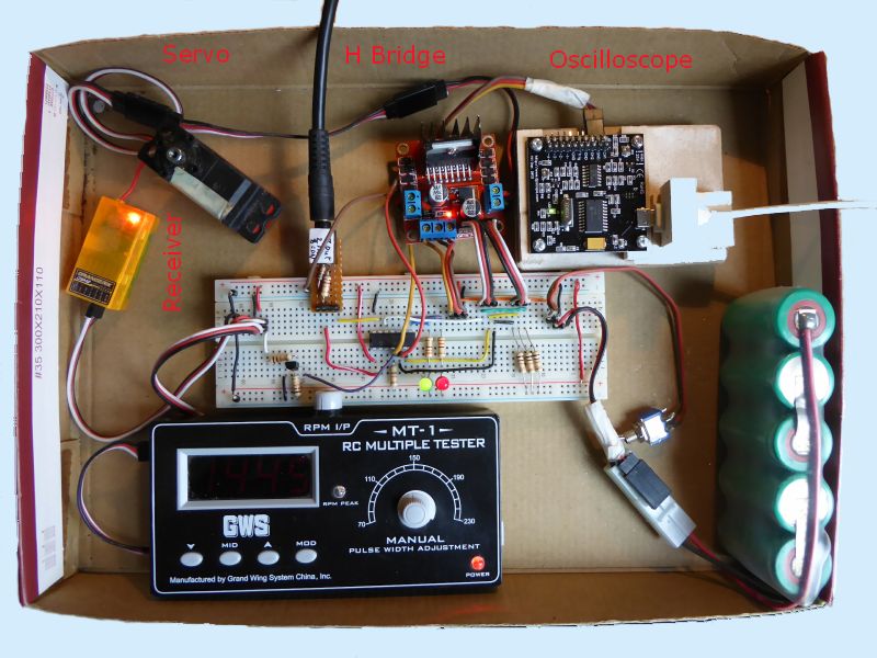
Prototype breadboard setup shows the Picaxe oscilloscope hardware costing £12. The pulse trace shows the high and low values which are similar to the more accurate meter readings
Spektrum Dx5e/Orange RX. Ch5 Gear switch = 1102 and 1849us.
13b. Variable inputs Ch3 throttle
In this test, the transmitter’s throttle joystick is used as it has no central point. Receiver is channel 3.
The circuit and code remains the same as the previous test 13a.
Red = 0 - 135 and Green = 165 - 190.
As expected, the section between 135 and 165 was being read as “0” pulse and the red led stayed on.
To solve this, new code was added to positively turn off both leds between 135 and 165.
if w1 > 135 and w1< 165 then noled 'if w1 is more than 135 & less than 165 then no LED
noled:
low C.1 'pin 6 switch off LED green
low C.2 'pin 5 switch off LED red
goto main 'loop
This caused a problem as both red and green leds flashed together at the change points.
The Picaxe reads the input pulse to the nearest 10us. The meter readings show that it is easy to position the joystick at the middle of the change position so it is neither or both resulting in both leds flashing on.
I have no experience to know if this happens in real life but is useful to know if you find both events happening at the same time at the change over position.
The point of change between on and off was a noticable 10us and could be found by moving the joystick. Both leds flashing
13c. Increasing frequency to improve accuracy
Frequency
The 10us pulse width is determined by the Picaxe’s 4MHz frequency so the test was run again with the frequency raised to 16MHz by adding code “setfreq m16”.
This gives a pulse width four times faster at 2.5us. The cut off point values have to be multiplied by four. The “pulsin” value is more than 255.
w1 not b1.
In previous coding b1 was used, b signifying a BYTE variable which can only hold integers/numbers between 0 and 255. w1 is a WORD variable holding 0 to 65535 and has to be used here.
[CODE]
init:
setfreq m16
w1 = 0
main:
pulsin C.3, 1, w1
if w1 < 540 then redled
if w1 > 539 and < 661 then noled '1us overlap
if w1 > 660 then greenled
redled:
low C.1
high C.2
goto main
greenled:
high C.1
low C.2
goto main
noled:
low C.1
low C.2
goto main
[/CODE]
| Equal | Gap 1 | Overlap 1 | ||||
|---|---|---|---|---|---|---|
| Code | value | Code | value | Code | value | |
| Red solid | 0 - | 0 - 1343 | 0 - | 0- 1350 | 0 - | 0 - 1342 |
| Red flashing | 540 | 1344 - 1347 | 540 | 1351 - 1353 | 540 | 1343 - 1345 |
| OFF | 540 - 660 | 1348 - 1640 | 541 - 659 | 1354 - 1640 | 539 - 661 | 1346 - 1644 |
| Red flashing | 660 - | 1641 - 1642 | 660 | 1641 - 1643 | 660 | |
| Red solid | 1643 - 1645 | 1644 - 1650 | ||||
| Green flashing | 1642 - 1645 | 1648 - 1650 | 1645 - 1647 |
|||
| Green solid | 760 | 1646 - 1896 | 760 | 1651 - 1896 | 760 | 1648 - 1896 |
Increasing the frequency and overlapping the values by 1us appears to solve the problem. Moving the joystick does not pick up the flashing leds at the change point. The 2us flashing band is smaller than the joystick movement accuracy.
Remember that the code values are totally dependent on the receiver’s output. Trial and Error.
This increase in accuracy may be useful for certain applications.
13d. ch4 joystick centre
Servos need a central off position which has a narrow pulse width band called the “Deadband” which range from 4 to 7us. The manufacturers specify their servo central position to be 1500/1510us. Unfortunately in real life this value can vary from 1390 to 1590us. Again, trial and error will be needed.
A yellow led has been added to simulate the Deadband from C.4 and “noled” code changed to “yellowled”.
[CODE]
init:
setfreq m16
w1 = 0
main:
pulsin C.3, 1, w1
if w1 < 561 then redled
if w1 > 559 and < 581 then yellowled
if w1 > 579 then greenled
redled:
low C.1
high C.2
low C.4
goto main
greenled:
high C.1
low C.2
low C.4
goto main
yellowled:
low C.1
low C.2
high C.4
goto main
[/CODE]
Joystick movement about the central position is not accurate. If you let the stick spring back to the centre you get 1410us one side and 1430 the other so a wide deadband is necessary.
The critical thing is that the stick must always turn off the servo or motor. Again, trial and error. Set the joystick trim button centrally before you start then use it to fine tune the position at the end. 200us variation for throttle Ch3.
13e. ch4 motor control H Bridge
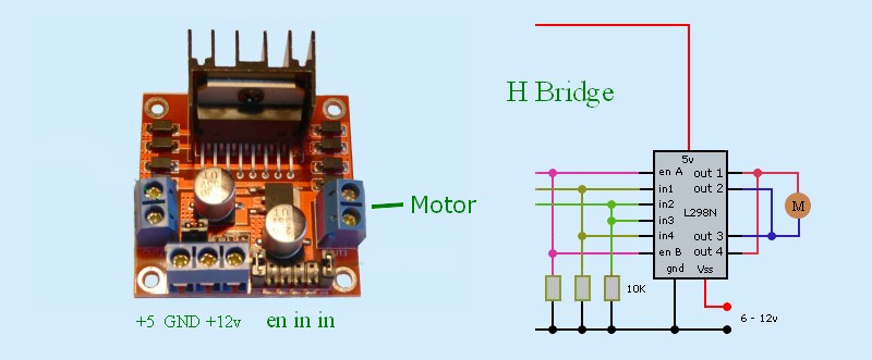
L298N is the H Bridge module which sends the correct voltage pulse to control the motor’s speed and direction. It also includes a series of diodes to stop the motor generating a back EMF when power is removed from the motor.
The central deadband is easy as everything is off. The motor speed increases either side so the coding is positive going forwards and negative for reverse.
The second consideration is that the motor should not be run below 50% speed drop. Below this can stall the motor and increase the current drain.
For example servo Acd1 % speed drop is;
No load 0% = 0.2A. 10% = 0.5A. 30% = 0.7A 60% = 1.0A 100% = 2.2A stall
H Bridge setup
12v Jumper. Only remove if using over 12v. (Note, voltage supply specified as 12v on the PCB)
EN Jumpers. Remove. (only used with stepper motors)
It is possible to alter the rate at which the motor speed increases from a linear straight line to a curve between 0 and max. Starting very slowly and then rapidly increasing.
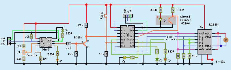
13f Ch4 Motor controller
These two tests use previous codes but with Ch4 Rudder as it has the central off position.
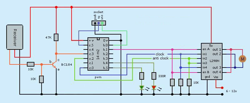
This test uses a 14m2 Picaxe with a dual L298N H Bridge module to control a single motor from a Tx/Rx receiver. The frequency is left at 4MHz to reduce complications.
Picaxe Oscilloscope is used to check and calibrate the receiver input into pin c.3. It is possible to measure the pulse width in msec from the bottom tool bar. It can also be used as a volt meter to check outputs.
6.2v battery is used to supply the motor via the H Bridge driver with 5v supplied to the Picaxe and receiver from its onboard voltage regulator.
Normally the receiver will be used to control other servos and will be supplied by its own source. In that case, the red +ve supply in the receiver/picaxe cable must be cut at X.
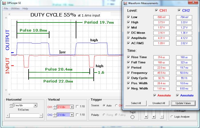
The PWM pulse from the receiver into the Picaxe is significantly different to the PWM pulse from the Picaxe to the H Bridge drive. (See below).
Receiver PWM has a pulse from 1.0ms to 2.0ms repeated every 20ms. (approx).
H Bridge outputs a regular pulse with its width controlling the motor speed. At half power the pulse is only on for half the time.
H Bridge setup
12v Jumper. Remove if using over 12v. (Note, voltage supply specified as 12v on the PCB)
EN Jumpers. Remove. (only used with stepper motors)
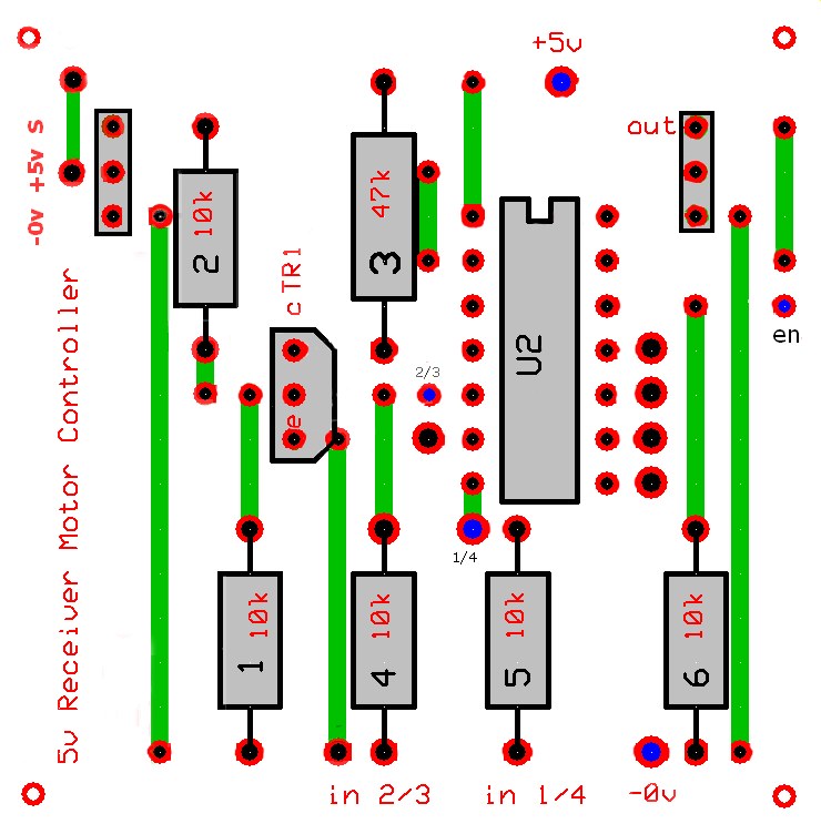
Dirs
The ports on the 14m2 have to be specified as in or outputs. The two PWM outputs to the H Bridge showed correctly working voltages but the motor would not run. It did when I set pin b.1 enable to an output
dirsb%00110011, 0 = input and 1 = output. Port numbers run 7,6,5,4,3,2,1,0
b.0, 1, 4, 5 are outputs. Ports 2 and 3 are not used so either 1 or 0 is correct
c.1, 2 are outputs and c.3, 5 inputs. c.0, 4 not used = 00000110
Port numbers not on picaxe are 0
Waveform
This shows the input and output waveforms with the joystick just on forwards at 1600us and just before the output goes high at 1800ms. The input waveform goes downwards because transistor between the receiver and Picaxe inverts the input signal. The signal is measured from the trailing edge.
Symbol names may remain black when you write them. Just check your code and they should turn blue.
If you have previously used the USB cable for the oscilloscope you might find you cannot upload a programme if the cable is installed. Odd.
I found that you could not uses word variables above w13. Odd.
w1 < 100 — less than 100
w1 > 100 — more than 100
13g. ch4 3 position motor control
This test is to make a motor run slowly, medium and fast in one direction with three joystick positions. Left, centre, right.
Motors may not turn with a duty cycle below 50%. This minimum value can be found by trial and error.
It becomes confusing when you start to use a lot of pin numbers c.2, b.5, so we replace the number with a name and use “symbol”
e.g. Symbol redled = b.4
Many pins can be used as either inputs or output but in certain cases they must be specified. This programme would only work if b.1 enable was made an output
“dirs = %00000000” sets the pins to input/output. Remember that 0 is input and 1 is output. See code below>
Only one pwm output c.0 or c.2 can be used at one time. c.0 makes the motor clockwise and c.1 backwards. Servos are specified as either cw or ccw so you may have to swap outputs.
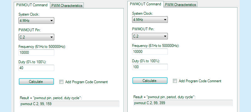
pwmout c.2, 99, 0 sets the period at 99 and duty cycle at 0.
This information come from the Picaxe — Wizard — pwm calculator.
Leave the frequency at 10000Hz and clock to 4Mhz. Change PWMOUT pin to your output pin.
[CODE]
init:
symbol enable = b.1
symbol redled = b.4
symbol greenled = b.5
dirsb=%00110011 ; x, x, out, out, x, x, x, out, 1 = output 0 = input.
dirsc=%00000100 ; x, x, in, x, in, out, x, x
w1 = 0
pwmout c.2,99, 0
main:
pulsin c.3, 0, w1
if w1 < 135 then slo
if w1 > 135 and w1 < 165 then med
if w1 > 165 then ful
slo:
high enable
high c.2
hpwmduty 240 ;duty 60%, stall @50%, h has to be added to pwmduty
high redled
low greenled
goto main
med:
high enable
high c.2
hpwmduty 320 ;duty 80%
high redled
high greenled
goto main
ful:
high enable
high c.2
hpwmduty 400 ;duty 100%
low redled
high greenled
goto main
[/CODE]
H Bridge input pulses at three fixed positions
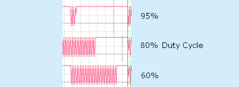
The upper continious red line is maximum power/voltage being delivered to the motor. It is a straight line at 100%. At lower duty cycles continious power is replaced by pulsed votltage until at 50% it is a continiously pulsed. At this point the motor is getting insufficient power/voltage to turn.
14. Throttle Ch3 controlling motor speed in one direction
These two tests look at controlling the motor speed increase either in a straight line (linear) or a curve (non – linear). The latter allows for greater control at low speeds but requires a lot of coding to make changes. Linear only requires min/max input values and min/max duty cycles.
Ch3 Throttle is used as it has no sprung central off position.
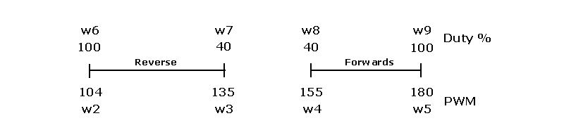
14a Ch3 Linear speed increase. Off – max forwards
With this code, the motor speed increases is linearly and can be easily altered to suit different receivers.
[CODE]
; Ch3 throttle output 1203 to 1898
; b1 enable
; b.4 redled
; b.5 greenled
; c.0 reverse direction
; c.2 forwards direction
init:
dirsb=%00110011
dirsc=%00000100
pwmout c.2, 99, 0
w1 = 0 ; variable input
main:
pulsin c.3, 0, w1
w2 = 120 ; min speed joystick position
w3 = 180 ; max speed joystick position
w4 = 150 ; min duty cycle
w5 = 400 ; max duty cycle
w6 = w5 - w4 ; 400 - 150 = 250
w7 = w3 - w2 ; 180 - 135 = 45
w8 = w6 / w7 * 10 ; 250/45 x 10 = 56, x 10 variables ignore decimal part of value
w9 = w1 - w2 ; 157 - 135 = 22 ; 157 test value
w10 = w9 * w8 /10 ; 22 x 56 / 10 = 123, /10 to remove previous x 10
w11 = w10 + w4 ; 224 + 150 = 273. mid point = 275
if w1 < 120 then fwdoff
if w1 > 110 and w1 < 185 then fwdon
if w1 > 180 then fwdfull
fwoff: low b.1 : low c.0 : low c.2 : pwmduty c.2, 0 : high b.4 : low b.5 : goto main
fwdon: high b.1 : low c.0 : high c.2 :pwmduty c.2, w11 : low b.4 : high b.5 : goto main
fwdfull: high b.1 : low c.0 : high c.2 :pwmduty c.2, 400 : high b.4 : high b.5 : goto main
[/CODE]
14b. Ch3 Linear speed decrease. Max reverse – off
; variable reverse
; Ch3 throttle input 1003 to 1898
; b1 enable
; b.4 redled
; b.5 greenled
; c.0 reverse direction
; c.2 forwards direction
init:
dirsb=%00110011
dirsc=%00000101
pwmout c.0,99, 0 ; reverse
pwmout c.2,99, 0 ; forwards
w1 = 0 ; variable input
main:
pulsin c.3, 0, w1
w2 = 135 ; min speed position
w3 = 180 ; max speed position
w4 = 150 ; min duty cycle
w5 = 400 ; max duty cycle
w6 = w5 - w4 ; 400 - 150 = 250
w7 = w3 - w2 ; 180 - 135 = 45
w8 = w6 / w7 * 10 ; 250/45 x 10 = 56 No decimal variables
w9 = w3 - w1 ; 180 - 157 = 23 ; 157 test value mid point
w10 = w9 * w8 /10 ; 23 x 56 / 10 = 129
w11 = w10 + w4 ; 129 + 150 = 279 ; mid point = 276
if w1 < 135 then revfull
if w1 > 135 and w1 < 180 then revon
if w1 > 170 then revoff ; 10 overlap
revfull: high b.1 : high c.0 : low c.2 : pwmduty c.0, 400 : high b.4 : high b.5 : goto main
revon: high b.1 : high c.0 : low c.2 : pwmduty c.0, w11 : low b.4 : high b.5 : goto main
revoff: low b.1 : low c.0 : low c.2 : pwmduty c.0, 0 : high b.4 : low b.5 : goto main
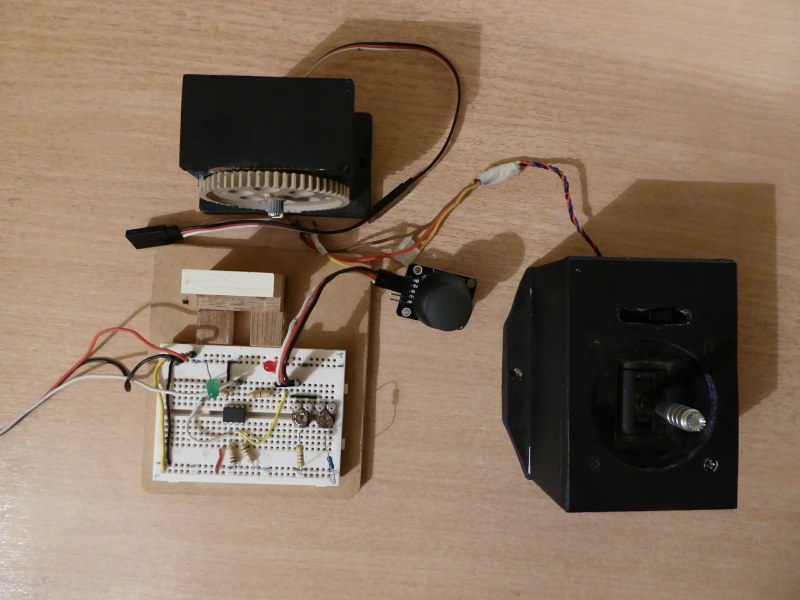
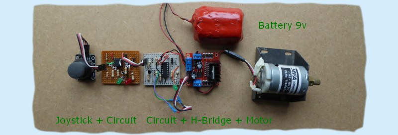
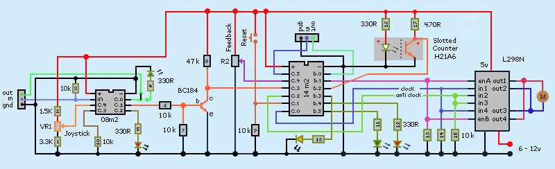
15. R/C controlling motors
This uses previous coding and the L296N H Bridge motor control module to drive a motor as a servo. This introduces positive feedback.
My objective is to control the main sail sheet of my very large 1/10 scale French Pilot cutter the Jolie Brise. The sheet travle is 600mm and its load is about 4kg. There is nothing on the market or incorporates “Captive Drum Technology”.
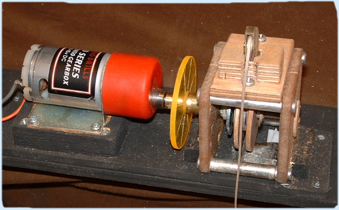
The yellow slotted disc is to optically count the number of turns to provide fully in to fully out control. About 7 turns.
A 10:1 geared 5k variable resistor may be used to provide postional feedback.
My original intention was to use the slotted disc for this function to simplify the design doing away with the gearbox and all its supports and wiring.
Motor spec
Motor MFA919D. 100:1. 6kg.cm. 119rpm at 9v. Drum 15mm dia. 47mm circumference. 8kg sheet load. 1.1sec/100mm. 600mm sheet travel @ 6.6sec. Average PWM input pulse 1.1 to 1.9ms = 0.8ms.
15a. Ch4 Linear speed forwards - central off [half code]
; Ch4 throttle input 116 to 155/157 to 190
; b1 enable
; b.4 redled
; b.5 greenled
; c.0 reverse direction
; c.2 forwards direction
init:
dirsb=%00110011
dirsc=%00000101
pwmout c.0,99, 0
pwmout c.2,99, 0
w1 = 0 ; variable input
main:
pulsin c.3, 0, w1
w2 = 157
w3 = 180
w4 = 150
w5 = 400
w6 = w5 - w4
w7 = w3 - w2
w8 = w6 / w7 * 10
w9 = w1 - w2
w10 = w9 * w8 /10
w11 = w10 + w4
if w1 < 157 then fwdoff
if w1 > 157 and w1 < 185 then fwdon
if w1 > 180 then fwdfull
fwdoff: low b.1 : pwmduty c.0, 0 : pwmduty c.2, 0 : high b.4 : low b.5 : goto main
fwdon: high b.1 : pwmduty c.0, 0 : pwmduty c.2, w11 : low b.4 : high b.5 : goto main
fwdfull: high b.1 : pwmduty c.0, 0 : pwmduty c.2, 400 : high b.4 : high b.5 : goto main
15b. Ch4 Linear speed reverse - central off [half code]
; Ch4 throttle input 116 to 155 / 157 to 190
; b1 enable
; b.4 redled
; b.5 greenled
; c.0 reverse direction
; c.2 forwards direction
init:
dirsb=%00110011
dirsc=%00000101
pwmout c.0,99, 0
pwmout c.2,99, 0
w1 = 0
main:
pulsin c.3, 0, w1
w2 = 120
w3 = 155
w4 = 150
w5 = 400
w6 = w5 - w4
w7 = w3 - w2
w8 = w6 / w7 * 10
w9 = w3 - w1
w10 = w9 * w8 /10
w11 = w10 + w4
if w1 < 120 then revfull
if w1 > 130 and w1 < 150 then revon
if w1 > 145 then revoff
revfull: high b.1 : high c.0 : low c.2 : pwmduty c.0, 400 : high b.4 : high b.5 : goto main
revon: high b.1 : high c.0 : low c.2 : pwmduty c.0, w11 : low b.4 : high b.5 : goto main
revoff: low b.1 : low c.0 : low c.2 : pwmduty c.0, 0 : high b.4 : low b.5 : goto main
15c. Ch4 Linear speed reverse – central off – forwards
Combination of codes 15a & b
[CODE]
; Ch4 throttle input 116 to 155 / 157 to 190
symbol enable = b.1
symbol redled = b.4
symbol greenled = b.5
symbol rvsduty = c.0 ; reverse direction
symbol fwdduty = c.2 ; forwards direction
init:
dirsb=%00110011
dirsc=%00000101
pwmout c.0,99, 0 : pwmout c.2,99, 0
w1 = 0
main:
pulsin c.3, 0, w1
if w1 < 100 then revfullon
if w1 > 95 and w1 < 145 then revvariable
if w1 > 140 and w1 < 160 then revfwdoff
if w1 > 155 and w1 < 205 then fwdvariable
if w1 > 200 then fwdfullon
;------- REVERSE FULL ON-------------
revfullon:
high enable : pwmduty rvsduty, 400 : pwmduty fwdduty, 0 : low redled : high greenled : pause 100 : goto main
;--------REVERSE VARIABLE -----------
revvariable:
w2 = 120 : w3 = 155 : w4 = 130 : w5 = 400
w6 = w5 - w4
w7 = w3 - w2
w8 = w6 / w7 * 10
w9 = w3 - w1
w10 = w9 * w8 /10
w11 = w10 + w4
high b.1 : pwmduty rvsduty, w11 : pwmduty fwdduty, 0 : high redled : low greenled : pause 100 : goto main
;---------- OFF -----------------
revfwdoff:
low enable : pwmduty c.0, 0 : pwmduty fwdduty, 0 : high redled : high greenled : pause 100 : goto main
;---------- FORWARDS VARIABLE --------
fwdvariable:
w2 = 157 : w3 = 180 : w4 = 130 : w5 = 400
w6 = w5 - w4
w7 = w3 - w2
w8 = w6 / w7 * 10
w9 = w1 - w2
w10 = w9 * w8 /10
w11 = w10 + w4
high enable : pwmduty rvsduty, 0 : pwmduty fwdduty, w11 : low redled : high greenled : pause 100 : goto main
;------------- FORWARD FULL ON ----------
fwdfullon:
high enable : pwmduty rvsduty, 0 : pwmduty fwdduty, 400 : high redled : low greenled : pause 100 :goto main
[/CODE]
15d Ch4 Non linear speed increase. Off — max forwards [half code]
In this test, the throttle varies the motor speed from zero to maximum in one direction with an initial off deadband.
The principles of the last test are used with small steps and the duty cycle length increases gradualy from zero upto max.
I had to go back and increase the frequency to 16MHz and overlap the values.
It worked without glitches between the individual steps. More steps can be added to make the speed increase smoother.
Advantage: The rate of speed change can be varied to give more control at slow speeds.
[CODE]
init:
init: setfreq m16
symbol enable = b.1
symbol redled = b.4
symbol greenled = b.5
dirsb=%00110011
dirsc=%00000100
w1 = 0
pwmout c.2,99, 0
main:
pulsin c.3, 0, w1
if w1 < 520 then stp1 ;0
if w1 > 519 and w1<541 then stp2 ;200 duty cycles
if w1 > 539 and w1<561 then stp3 ;208
if w1 > 559 and w1<581 then stp4 ;220
if w1 > 579 and w1<601 then stp5 ;232
if w1 > 599 and w1<621 then stp6 ;244
if w1 > 619 and w1<641 then stp7 ;260
if w1 > 639 and w1<661 then stp8 ;276
if w1 > 659 and w1<681 then stp9 ;296
if w1 > 679 and w1<701 then stp10 ;328
if w1 > 699 and w1<721 then stp11 ;360
if w1 > 719 then stp12 ;400
stp1:
low enable
low c.2
hpwmduty 0
high redled
low greenled
goto main
stp2:
high enable
high c.2
hpwmduty 200
low redled
high greenled
goto main
Steps 3 to 12 similar to stp 2 except for the changing duty cycle.
[/CODE]
15e. CH4 Non – linear speed. Max reverse – off – Max forwards
Extension of 15d
init: setfreq m16
symbol enable = b.1
symbol redled = b.4
symbol greenled = b.5
dirsb=%00110011 : dirsc=%00000100
w1 = 0
pwmout c.2,99, 0
pwmout c.0,99, 0
main:
pulsin c.3, 0, w1
pause 100
if w1< 417 then rv6
if w1 > 415 and w1<441 then rv5
if w1 > 439 and w1<465 then rv4
if w1 > 463 and w1<493 then rv3
if w1 > 491 and w1<517 then rv2
if w1 > 515 and w1<541 then rv1
if w1 > 539 and w1<621 then stpoff
if w1 > 619 and w1<633 then fr1
if w1 > 631 and w1<646 then fr2
if w1 > 643 and w1<657 then fr3
if w1 > 655 and w1<668 then fr4
if w1 > 667 and w1<681 then fr5
if w1 > 679 then fr6
rv6: high enable : low c.2 : high c.0 : hpwmduty 400 : high redled : low greenled : goto main
rv5: high enable : low c.2 : high c.0 : hpwmduty 360 : high redled : low greenled : goto main
rv4: high enable : low c.2 : high c.0 : hpwmduty 320 : high redled : low greenled : goto main
rv3: high enable : low c.2 : high c.0 : hpwmduty 280 : high redled : low greenled : goto main
rv2: high enable : low c.2 : high c.0 : hpwmduty 240 : high redled : low greenled : goto main
rv1: high enable : low c.2 : high c.0 : hpwmduty 200 : high redled : low greenled : goto main
stpoff: low enable : low c.2 : low c.0 : hpwmduty 0 : high redled : high greenled : goto main
fr1: high enable : high c.2 : low c.0 : hpwmduty 200 : low redled : high greenled : goto main
fr2: high enable : high c.2 : low c.0 : hpwmduty 240 : low redled : high greenled : goto main
fr3: high enable : high c.2 : low c.0 : hpwmduty 280 : low redled : high greenled : goto main
fr4: high enable : high c.2 : low c.0 : hpwmduty 320 : low redled : high greenled : goto main
fr5: high enable : high c.2 : low c.0 : hpwmduty 360 : low redled : high greenled : goto main
fr6: high enable : high c.2 : low c.0 : hpwmduty 400 : low redled : high greenled : goto main
Copper Strip Prototype Board Top
Copper Strip Prototype Board Copper side
16. Servopos output to Servo
16. Servopos output to Servo
servo and servopos are used to output a PWM signal to a servo.
Values used are 80 to 220 = 0.8 to 2.2ms. If you go outside these values you can damage the servo either by hitting the end stops (90 deg arm servos) or by running continuously (drum servos).
The average receiver outputs 110 to 190 = 1.1 – 1.9ms = 0.8ms range.
pause is added to allow the servo to move to the next position. The 5sec pause used here is because the drum servo turned slowly.
servo is used to start the timer and create the correct 20ms frame rate.
This program directly controls the servo movement.
servo — Man 2 pg 204
servopos — Man 2 pg 206
init:
servo 1, 100 ; initialises timer and sets servo to 100 = 1000µsec = 1.0ms
main:
servopos 1, 100 ; sets servo to 1000µsec
pause 5000 ; pauses for 5 sec
servopos 1, 150
pause 5000
servopos 1, 200
pause 5000
servopos 1, 150
pause 5000
goto main

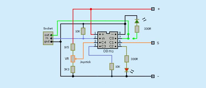
16a. Joystick output to Picaxe
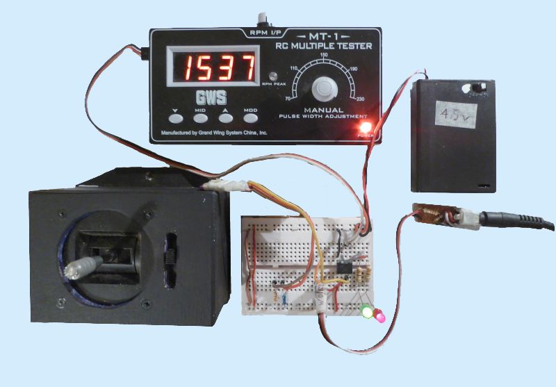
In this section I wanted to stop using a transmitter/receiver and directly control the motor with a centrally sprung joystick taken from a redundant transmitter. The 08m2 chip is used to convert the voltage produced by the joystick’s Variable Resistor into a PWM pulse to control a motor.
Red led shows when the joystick is in reverse mode and green in forwards. Both leds on in neutral.
The 10K resistor grounding "Serial In" was added as I was having problems getting a stable output. It would take 30 seconds to connect and then flick on and off.
There were still problems getting a steady output pulse without the signal momentarily going to zero making the motor stutter. I tried all sorts solutions such as changing the wire and component positions in the prototype board as there can be continuity problems. Picaxe, power source, variable resistors and pulse meters were tried with no effect. Removing the Led's and its coding made no difference.
A collegue suggested adding smoothing capacitors. 1uF capacitors were added to smooth the power supply and voltage into the acd input c.4. I tried values up to 200uF. Somebody suggested placing a 1N4148 diode in the +ve supply line to demove -ve spikes. None of these solutions worked.
Then I posted a message on the Picaxe forum. hippy's solution was to add a PAUSE 100. This worked. Also suggested, for good practice, was to set the servo initial value to something other than 0, I used the joystick central position 158.
[CODE]
init:
b1 = 0
servo c.1, 158
main:
readadc c.4, b1
servopos c.1, b1
pause 100
if b1<148 then redled
if b1 > 143 and b1 <165 then redgreenled
if b1 >158 then greenled
redled:
high c.2
low c.0
goto main
redgreenled:
high c.0
high c.2
goto main
greenled:
low c.2
high c.0
goto main
[/CODE]
The original circuit had no resistors either side of the joystick Variable Resistor. Unexpectedly, the 08m2 gave an PWM output on C.1 of 0.26 to 2.1ms .
Various resistors were added to see what happened and the values chosen that gave a 1500us central position and 930us range which suited the previous coding for the motor controller.
Joystick VR spec.
45 deg movement. Usable 2.54K, Range = 1.12 to 3.66K, Trim = 0.4K +/-, red/orange/black.
Joystick positions:
Minimum 1050ms PWM pulse. 1.98 volts on c.4
Central 1500ms. 2.86 volts on c.4
Maximum 1980ms. 3.76 volts on c.4
Use 5K preset variable resistors for more accurate setting.
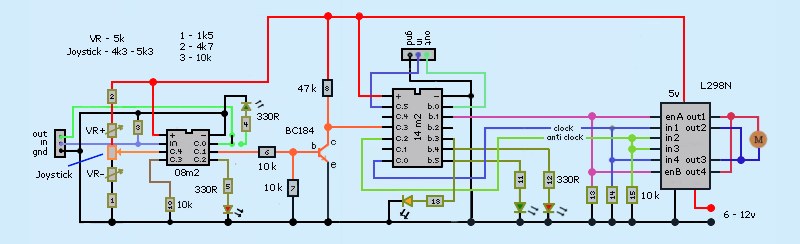
16b. Joystick and variable resistors control circuit
Varying resistance of input devices showed a range between 4.37K and 5.24K. Existing circuit could not output a consistent PWM pulse to feed into the motor control circuit.
The circuit was changed by adding 5k preset variable resistors either side of the joystick/potentiometer. Two fixed resistors 1k5 and 4k7 have been added to avoid current overload if input resistance went to zero.
Various fixed and variable resistors were tried to produce a PWM pulse of 1s to 2s. The motor circuit will have to be altered to give the motor linear forwards and reverse speed over the full range.
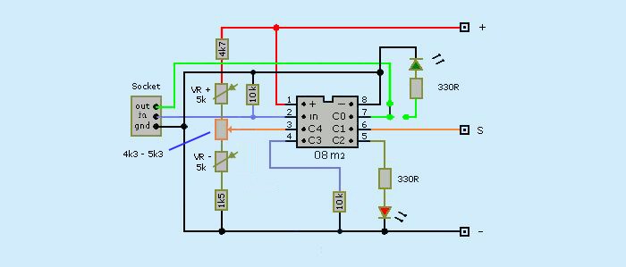
On thr right is a joystick made from CH3 transmitter throttle 4R3. In the middle is a small joystick used with PCB's 4K6. At the top is a standard 5k potentiometer in a housing 5k3,
16c. Joystick controlling motor
Combination of two circuit boards
14m2 Motor Control PCB CODE
pause 100 has been added to remove glitches when changing speed.
symbol enable = b.1
symbol redled = b.4
symbol greenled = b.5
symbol rvsduty = c.0 ; reverse direction
symbol fwdduty = c.2 ; forwards direction
init:
dirsb=%00110011
dirsc=%00000101
pwmout c.0,99, 0 : pwmout c.2,99, 0
w1 = 0
main:
pulsin c.3, 0, w1
if w1 < 100 then revfullon
if w1 > 95 and w1 < 145 then revvariable
if w1 > 140 and w1 < 160 then revfwdoff
if w1 > 155 and w1 < 205 then fwdvariable
if w1 > 200 then fwdfullon
;------- REVERSE FULL ON-------------
revfullon:
high enable : pwmduty rvsduty, 400 : pwmduty fwdduty, 0 : low redled : high greenled : pause 100 : goto main
;--------REVERSE VARIABLE -----------
revvariable:
w2 = 120 : w3 = 155 : w4 = 130 : w5 = 400
w6 = w5 - w4
w7 = w3 - w2
w8 = w6 / w7 * 10
w9 = w3 - w1
w10 = w9 * w8 /10
w11 = w10 + w4
high b.1 : pwmduty rvsduty, w11 : pwmduty fwdduty, 0 : high redled : low greenled : pause 100 : goto main
;---------- OFF -----------------
revfwdoff:
low enable : pwmduty c.0, 0 : pwmduty fwdduty, 0 : high redled : high greenled : pause 100 : goto main
;---------- FORWARDS VARIABLE --------
fwdvariable:
w2 = 157 : w3 = 180 : w4 = 130 : w5 = 400
w6 = w5 - w4
w7 = w3 - w2
w8 = w6 / w7 * 10
w9 = w1 - w2
w10 = w9 * w8 /10
w11 = w10 + w4
high enable : pwmduty rvsduty, 0 : pwmduty fwdduty, w11 : low redled : high greenled : pause 100 : goto main
;------------- FORWARD FULL ON ----------
fwdfullon:
high enable : pwmduty rvsduty, 0 : pwmduty fwdduty, 400 : high redled : low greenled : pause 100 :goto main
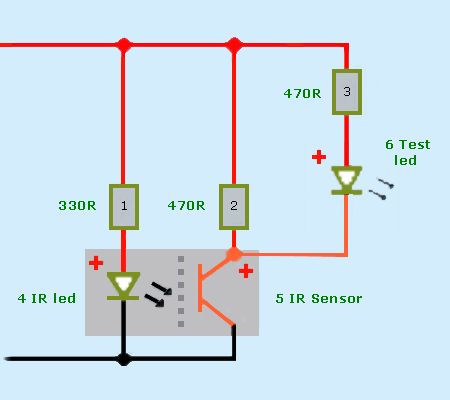
17. Photo Interrupter
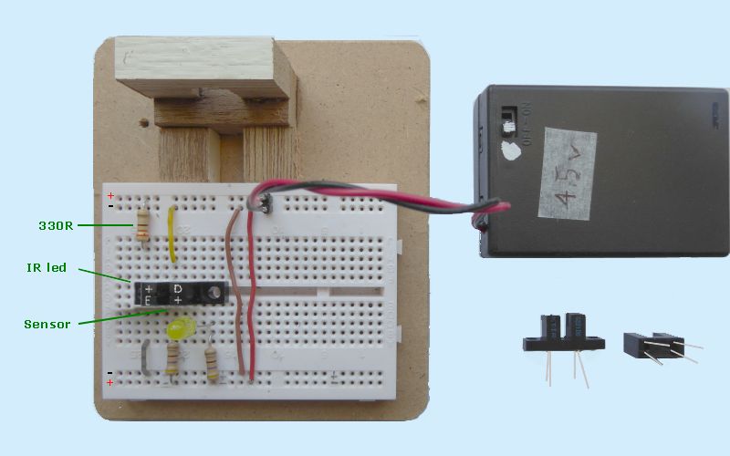
The first problem I encountered was finding out how to connect it into the circuit. It appears others have the same problem. In the end I ignored the dirgram in the data sheet and went back to a basic principles of LED’s that their legs have different lengths.
PLANS = Positive is Long and Negative is Short.
The infraRed led is marked with +/E or diode sign. The Long leg goes to Positive rail through a 330R resistor. Short leg goes directly to negative rail.
The InfraRed sensor is marked with D/+ or C/E. The Long leg goes to Positive rail through a 470R resistor and the High/Low output signal to Picaxe. Short leg goes directly to negative rail.
The additional led and resistor were used to test the circuit. The led goes on (high) when there is nothing in the gap.
KTIR0221DS & KTIR0621DS (Darlington) with Power supply = 4.2v.
R1 = 330R, 2.98v, 9ma.
R2 = 470R, 3.29v, 7ma.
R3 = 470R, 1.44v, 3ma.
D4 = 1.15v.
D5 = 2.42/0.83 off/on.
D6 = 1.85v.
18. Slotted disc turn counter. TBA
The joystick code above is added to the motor driver code 14d.
19. Variable resistor feedback loop. TBA
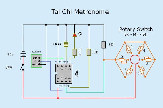
20. Metronome for Tai Chi
Breathing is one of the features of Tai Chi as it requires a steady rhythm of breathing in and out to match the sequence of movements. Think of Tai Chi as slow ballet.
Metronome set their “Beats” in beats per minute BPM, commercial metronomes only go down to 30 bpm.
I need to measure the time in seconds for one single breath either in or out. Studying clips of “18 step Shabashi” and others on You Tube gave me a wide range of times from 2.5 to 5.5 sec. This corresponds to 24 to 11bps. I also timed the beats in music used for Tai Chi and found 16bpm was the common number.
YouTube 18 Step Shabashi
Online Metronome giving 20 to 11 bpm
The times are set by a 6 pole rotary switch (break – make – break), 3.0, 3.5, 3.75, 4.0, 4.5, 5.0sec.
Each leg goes to variable resistors making one side of a potential divider with a fixed 4k7 resistor to ground. C.4 is the Readadc input. The table below sets out the calculations.
| No | BMP | Breathe in or out | READADC | PIN3 v | VR k | Pin3 k | Pause |
|---|---|---|---|---|---|---|---|
| 1 | 12 | 5.00 | 240/230 | 4.98 | 5k0 | 9k7 | 4950 |
| 2 | 13 | 4.61 | 200/190 | 4.15 | 4k2 | 8k9 | 4450 |
| 3 | 15 | 4.00 | 150/140 | 3.33 | 3k3 | 8k0 | 3950 |
| 4 | 16 | 3.75 | 110/100 | 2.49 | 2k5 | 7k2 | 3250 |
| 5 | 17 | 3.53 | 55/50 | 1.66 | 1k2 | 5k9 | 3450 |
| 6 | 20 | 3.00 | 27/17 | 0.82 | 0k8 | 5k5 | 2950 |
[CODE]
init:
b1 = 150
main:
readadc c.4, b1
pause 100
if b1 >17 and b1 <27 then beat20
if b1 >55 and b1 <55 then beat17
if b1 >110 and b1 <110 then beat16
if b1 >150 and b1 <150 then beat15
if b1 >200 and b1 <200 then beat13
if b1 >230 then beat12
beat20:
sound c.1, (50, 50)
high c.2
pause 2950
goto main
beat17:
sound c.1, (50, 50)
high c.2
pause 3480
goto main
beat16:
sound c.1, (50, 50)
high c.2
pause 3700
goto main
beat15:
sound c.1, (50, 50)
high c.2
pause 3950
goto main
beat13:
sound c.1, (50, 50)
high c.2
pause 4560
goto main
beat12:
sound c.1, (50, 50)
high c.2
pause 4950
goto main
[/CODE]